Auxiliary Component Drive System
The most important demand on any auxiliary unit drive system is slip-free drive for all auxiliary units, at all loading states, for the length of the engine’s useful life. In modern engines with full drives, it is thus possible, using the Micro-V® belts in a five- or six-rib design, to transfer maximum torques of up to 30 Nm and maximum power of from 15 to 20 kW with all the auxiliary units running at full load.
The ambient temperatures at 80 to 100°C on average are somewhat lower than in a synchronous belt drive. It is important to avoid, in particular, noises such as the well-known belt squeal caused in cold and damp weather by slippage between the belt and the pulley.
This is achieved with optimum system design in regard to the geometry and dynamics. It is also necessary to avoid belt noises caused by misalignment of pulleys, doing so right from the engineering stage. For auxiliary units, too, 240 000 km is taken today as the desired life expectancy in current engineering development work.
Design Criteria. Auxiliary unit drives are engineered with computer support.
A survey of the most important parameters to be considered in the design and some general engineering criteria are to be provided here. Important input data include the arrangement of the components (i.e., the drive configuration), torque development at the components, and the moments of inertia for the components as well as the data for the belt itself. With these data at hand, it is possible to calculate and optimize not only the span lengths and wrap angles, the system’s eigen frequencies, and the limit values for slip, but the belt’s lifetime as well.
Discussed below are a few general design criteria that must be observed in Micro-V® belt systems in order to engineer a functional system meeting today’s longevity expectations:
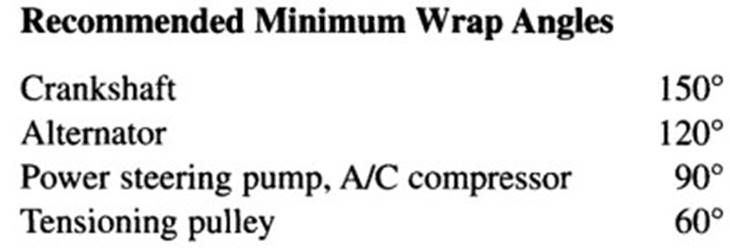
Alignment Error/Run-In Angle. In order to avoid unacceptable belt wear and noise, the belt's run-in angle into the grooved pulleys should not exceed 1°.
System eigen Frequency. The system’s eigen frequency should not be in the engine’s idle range (second engine order).
Minimum Diameters for Pulleys and Deflector Pulleys. In practice, the smallest pulley is often found at the alternator, which is needed to achieve the high rotation speeds required there. Typical alternator pulleys have a diameter of from 50 to 56 mm. Belt fatigue rises exponentially when small pulleys are used; this has to be taken into account when engineering the belt. It is advisable to use diameters of no less than 70 mm for deflection pulleys.
Belt Tensioning Systems. Belt tensioning in auxiliary unit drives is normally handled today with automatic tensioning pulleys. The tensioning pulleys ensure constant tension throughout the service life and compensate for belt stretch and belt wear. The design of the tensioning pulleys is determined essentially by the available installation area (Fig. 7-250).
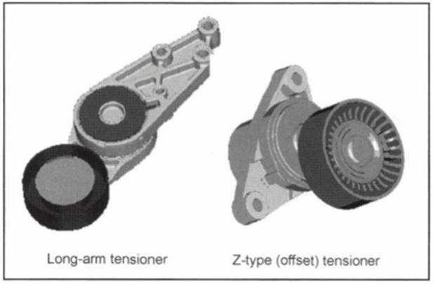
Fig. 7-250. Automatic belt tensioning systems
In long-arm tensioners the spring-and-damping system lies in the same plane as the belt drive system; where Z-type tensioners are used the tensioner housing is recessed into the area behind the belt drive. Preload is generated by a leg spring; the tensioner is friction damped at the same time. The preloads for 6 PK belts normally lie in a range of from 250 to 400 N, the exact value depending on the system’s dynamics.
Date added: 2024-05-31; views: 765;