Belt Drives Used to Drive Camshafts
Synchronous belt camshaft drives today hold a 75% market share in European engines. This can be traced essentially to advantages found in the simplicity of the drive concept, flexibility in belt guidance, low friction, and cost advantages when compared with other drive systems. Moreover, auxiliary units such as oil or water pumps can be integrated into the drive concept.
Synchronous Belt Drive. Design of the Synchronous Belt. The synchronous belt is a bonded system made of three components (Fig. 7-236):
- Nylon fabric
- Rubber blend
- Tensile member
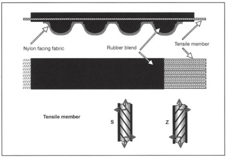
Fig. 7-236. Structure of the synchronous belt
The facing fabric is made of high-strength nylon and is coated to reduce wear. It protects the rubber teeth against wear and against their shearing off. The rubber blend is a high-strength polymer. Polychloropene (CR) was used in early versions. Because of stringent requirements in terms of dynamic strength and resistance to temperature and aging, HNBR (hydrogenated nitrile rubber) materials are used exclusively today.
The cords in the tensile member are made of glass fiber—a material distinguished by its great tensile strength and amenability to bending. Consequently, it is particularly well suited for camshaft drives in which the crankshaft sprockets are small in diameter. The manufacturing process is such that the strands in the tensile member are twisted, clockwise and counterclockwise, in pairs, in order to achieve largely neutral running properties for the belt.
The synchronous belt is manufactured using a vulcanization process. Specific coatings for the fabric and the tensile cords ensure bonds between the materials that will endure for the life of the engine.
Synchronous Belt Profile. There has been a significant evolution in the profiles used for synchronous belts since they were initially employed as timing belts. A wide variety of profiles are in use today. The various profiles and their properties are discussed below.
The first camshaft drive belts were based on the classical Power Grip design with its trapezoidal teeth, at that time already in widespread use in industrial applications. In response to increasing demands regarding power transmission, ratcheting resistance, and quiet running, curvilinear profiles (Power Grip® HTD/High Torque Drive) were developed. When compared with the trapezoidal shape, the forces are introduced more smoothly to the tooth with the rounder profiles, and this in turn reduces the possibility of tension peaks (Fig. 7-237). Rounded profiles are used exclusively today.
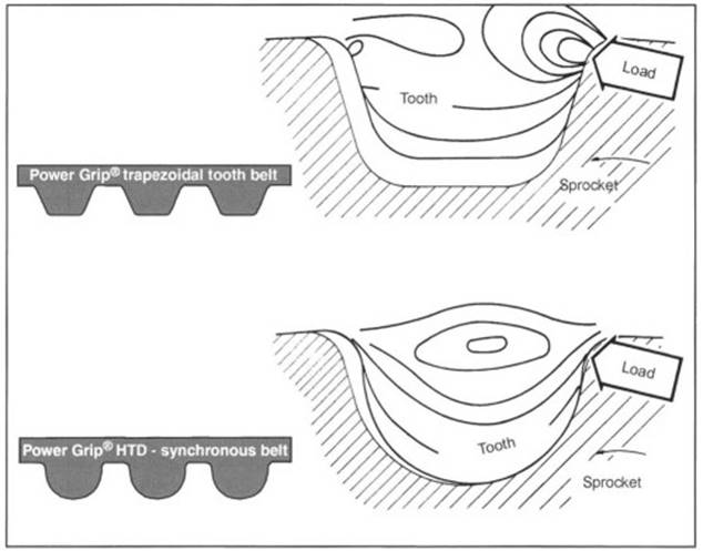
Fig. 7-237. Development of tooth profiles
In the first generation of synchronous timing belts— with the trapezoidal teeth—there were two different tooth shapes, the smaller “C tooth” for gasoline engines and the larger “B tooth” for diesel engines, each with a pitch of 9.525 mm (Fig. 7-238). This differentiation is no longer made in the newly developed HTD tooth profiles.
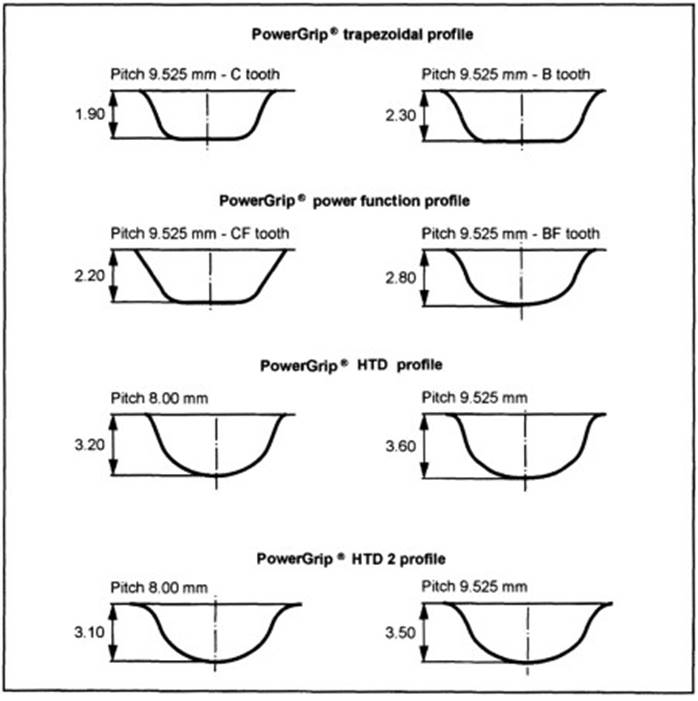
Fig. 7-238. Tooth profiles
When the HTD profile was introduced to the market, it was necessary to take into account the fact that some car makers continued to use the existing trapezoidal tooth sprockets.
To suit these applications, the profiles were optimized in regard to the radius at the root, flank shape, and tooth height (power function profile) so that they could be used with the existing trapezoidal sprockets. The associated sprockets, type ZA (C or CF tooth) and type В (В or BF tooth) are defined in ISO 9011.
HTD stands for the “high torque drive,” which was developed and patented by Gates. This curvilinear profile represented a considerable improvement in noise reduction, in power transmission, and, in turn, in terms of service life.
With the introduction of the succeeding HTD 2 generation, the existing advantages of HTD profiles were further enhanced. Here the radii at the root and the flank angles are once again enlarged.
Unique sprocket profiles are used for both types of profiles. The exact data for the profiles are available from Gates. Two pitch values are used for the two profiles: 9.525 and 8.00 mm. The smaller pitch has benefits in regard to noise and, because of the smaller sprocket diameter, permits a more compact design.
Both of the above-mentioned profiles can also be used in a double-sided synchronous belt (Fig. 7-239). Doublesided synchronous belts are used, for example, to drive balancer shafts.
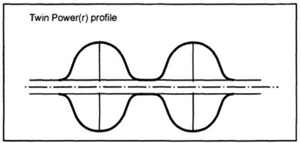
Fig. 7-239. Double-sided synchronous belts
Key Values—Synchronous Belts and Sprockets. The most important values for the synchronous belt are shown in Fig. 7-240. The height of the tooth and depth of the backing together give the overall thickness of the belt.
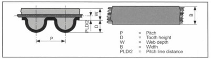
Fig. 7-240. Key values for toothed belts
The pitch line distance (the distance from the root of the tooth to the center of the tensile member) depends on the belt design, the thickness of the fabric, and the diameter of the tensile cords. The width of the synchronous belt is selected in accordance with the alternating dynamic loading; in internal combustion engines it normally lies between 20 and 28 mm and, in isolated applications, is as much as 32 mm.
Date added: 2024-05-31; views: 784;