Camshaft Shifter Systems
To comply with future exhaust gas regulations and to reduce fuel consumption, elements that influence valve timing are used more often in gasoline engines. The camshaft shifter is one such device. It enables continuous change in the timing for a camshaft, across a wide angular range. This makes possible a change in valve overlap in DOHC engines and thus influences the residual gas content in the combustion chamber.
In addition it is possible, above all at idle and full throttle, to tune timing for maximum comfort and/or maximum torque and highest performance. Camshaft shifters have been used in vehicles since the mid-1980s, initially as two-state shifters with simple controls but today more often as continuously adjustable systems operating under closed-loop regulation.
In DOHC engines, camshaft shifters are used mostly on the intake shaft; typical adjustment angles lie between 40 and 60 crankshaft degrees. There are, however, also shifters in mass production, used on the exhaust side, preferably in turbocharged engines. Both degrees of freedom may be combined where there are maximum demands regarding performance and exhaust gas quality.
In some DOHC engines camshaft shifters are used for dethrottling, i.e., reducing consumption by closing the intake valve late. In this concept, however, neither an increase in performance nor an improvement of comfort at idle can be achieved since the valve overlap is not changed.
Continuous camshaft shifting operates in a closed- loop regulation circuit and today is hydraulically powered in all cases.
In the engine management system, the required setpoint angle for timing adjustment is taken from an engine map dependent on load and speed. This is compared with the actual, measured angle. Deviations between the setpoint and actual angles are evaluated with a regulation algorithm and cause a change in the electrical power applied to the control valve. Thus, the valve diverts oil into the chamber at the valve shifter in a fashion corresponding to the desired adjustment direction, while oil is allowed to escape from the opposite chamber.
The angular position of the camshaft changes in accordance with the degree of fill at the oil chambers in the shifting unit. Sensors scan the trigger wheels at the camshaft and crankshaft; the actual value is calculated on the basis of these signals.
This regulation process runs continuously, at high frequency, and thus leads to good response characteristics when there are rapid changes in the set-point angle, giving high angular accuracy in maintaining the set-point angle. The system generally uses the motor oil circuit as its power supply; systems with a separate high- pressure supply are also found in sports engines.
The following components are needed to implement camshaft shifting:
- The hydraulic shifter unit, mounted on the drive end of the camshaft. This component sets the adjustment angle in response to alternating filling of two oil chambers. Low leak rates and sufficiently large piston surfaces ensure good stiffness under load. The shifter unit is built in various styles—with a linear piston and helical toothing or with a rotary piston.
- The regulation valve, built into the cylinder head or an attached component, should be located near the point at which oil is transferred to the camshaft. This valve is controlled electrically, usually with a pulse- width modulated signal; it regulates the flow of oil into and out of the chambers in the shifter unit. A high flow rate during adjustment phases and precise regulation capacities to fix the angle are the most important features of the valve.
- The regulation circuit for continuous adjustment comprises suitable software and a power output stage in the engine management unit as well as trigger wheels and sensors at the crankshaft and camshaft. Components already present in the engine can be used for this purpose, although the trigger wheel at the camshaft has to be modified.
The overall system for continuous camshaft shifting and the components described above are shown in Fig. 7-224.
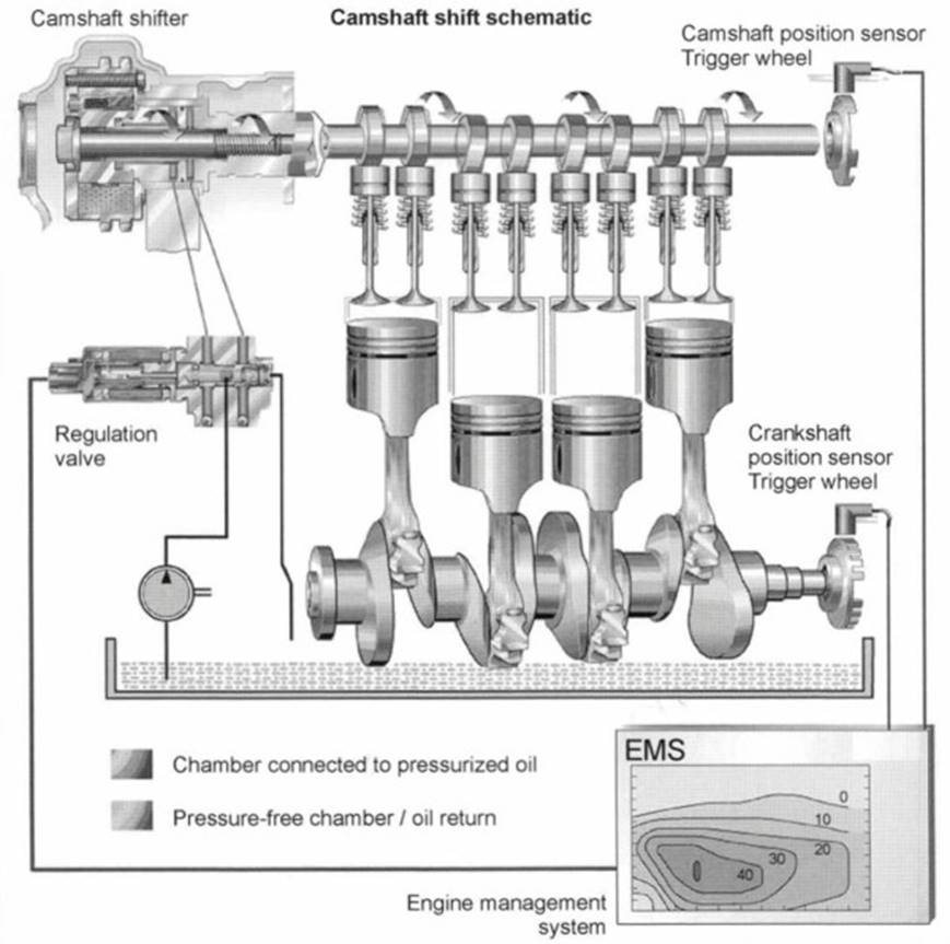
Fig. 7-224. Continuous camshaft shifting
Two concepts for the hydraulic shifter unit have become commonplace. A brief review of their basic design is provided below. The camshaft shifter with helical toothing comprises these main functional components: the drive sprocket (joined with the crankshaft), adjustment piston, and output hub (bolted to the camshaft).
These components are joined one with another in pairs, via helical inner toothing, so that an axial shift of the adjustment cylinder causes the drive hub to rotate in relationship to the drive wheel. The transfer of the torque using inner toothing is very rugged. The design shown in Fig. 7-225 is completely sealed, for use in toothed belt drives.
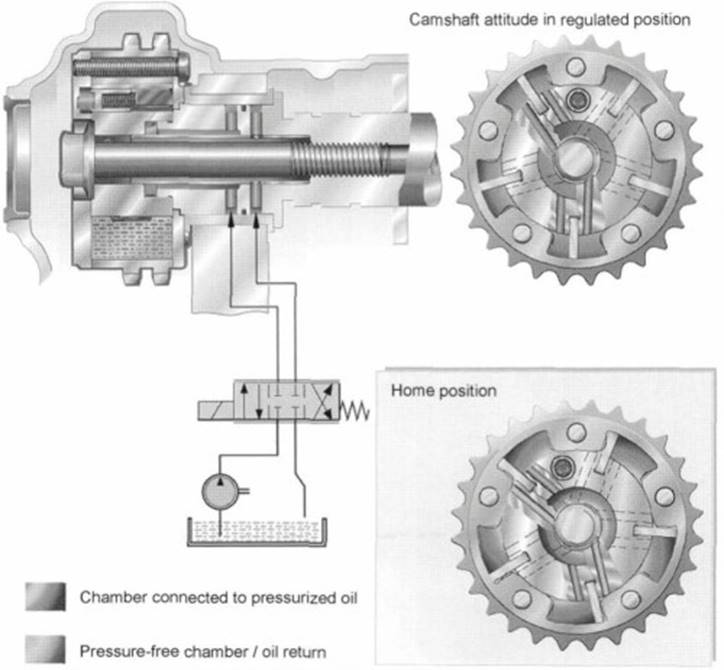
Fig. 7-225. Slewing motor or vane shifter
When the engine starts, the spring shown in the illustration keeps the shifting piston in its home position. Both chambers are filled with oil during regulated operation; good sealing between the two chambers provides good stiffness under load. Quick responses demanded by the engine are achieved with engine oil at a pressure of about 1.5 bar.
Shown in Fig. 7-226 is the slewing motor or vane shifter in a version for chain drive. This version of the camshaft shifter is more compact and economical than the version with helical toothing; it comprises only the drive gear and the output hub. Rotary torque is transferred during operations by the oil fill in the chambers.
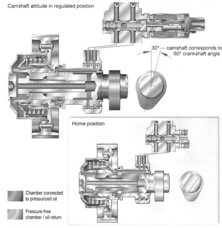
Fig. 7-226. Camshaft shifter with helical toothing
Only during engine starting does a locking element normally ensure a fixed mechanical link between the drive and output elements. This locking element is unlatched hydraulically once the camshaft shifter has filled with oil. The locked end position here is, as a rule, “late” timing when adjusting the intake camshaft and the “early” timing setting when adjusting at the exhaust camshaft.
The regulation valve comprises a hydraulic section and a solenoid. The hydraulic slider is located in a bore with connections for oil supply, actuator chambers for the camshaft shifter, and oil return. A spring moves the slider toward the home position. When power is applied to the solenoid, the slide is shifted against the force of the spring.
Bibliography: 1. Bensinger, W.-D., Die Steuerung des Gaswechsels in schnelllaufenden Verbrennungsmotoren, Konstruktionsbücher, Vol. 16, Springer-Verlag, 1967.
2. Holland, J., "Die instationäre Elastohydrodynamik," Konstruktion, Vol. 30, No. 9, 1978.
3. Ruhr, W., "Nockenverschleiss–Auslegung und Optimierung von Nockentrieben hinsichtlich des Verschleissverhaltens," FVV Research Project No. 285, 1985.
4. Holland, J., "Nockentrieb Reibungsverhältnisse–Untersuchung zur Verminderung der Reibung am Nocken-Gegenläufer-System unter Verwendung von Gleit- und Rollengegenläufern," FVV Research Project No. 341, 1986.
5. Brands, Ch., "Dynamische Ventilbelastung–Rechnergestützte Simulation der Beanspruchung des Ventiltriebs," FVV Research Project No. 614, 1998.
6. Dachs, A., Beitrag zur Simulation und Messung von Tassenstösselven-tiltrieben mit hydraulischem Ventilspielausgleich, Dissertation,Technical University of Vienna, 1993.
7. Ruhr, W., Nockentriebe mit Schwinghebel, Dissertation, Technical University of Clausthal, 1985.
8. Rahnejat, H., Multi-Body Dynamics, Vehicles, Machines and Mechanisms, SAE International, 1998.
9. Beitz, W., and K.-H. Küttner, Dubbel Taschenbuch des Maschinenbau, Springer-Verlag
Date added: 2024-05-31; views: 940;