Electrical Properties of the Cell and Ohm’s Law
Consider a simple hardwired electrical circuit such as that found in a hand-held torch or car battery (Figure 2(a)). The driving force for providing electrical current through this circuit illustrated in Figure 2(a) is a 12 V battery.
A copper wire that connects the two poles of the battery - the cathode and anode - acts as a conductor of the electrical current. The current is movement of charge in the form of electrons traveling along this conductor. The switch is a break in the wire that only allows current to flow when the circuit between the cathode and anode is complete.
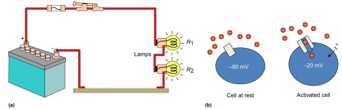
Figure 2. Electrical circuits: hardwired vs. biology. (a) Schematic diagram of an electrical circuit showing a car battery connected via a wire and switch to two car headlights/lamps. The battery has a different distribution of charges providing a negative and positive pole (cathode and anode, respectively) that drives current in the form of electrons through the wire conductor.
Current only flows when the switch is closed to complete the circuit. Current flows through the resistance provided by the lamp filaments, heating the filaments to cause the response – light. Available at: http://electricalengproject.blogspot.com.au/2012/06/electrical-circuits.html (accessed 17.02.15).
(b) In biology, the electrical battery is equivalent to the membrane potential with a negative charge (cathode) on the inside and a positive charge (anode) outside. When a switch (ion channel) is open, current in the form of charged ions can flow into the cell to cause a response – a depolarization
The resistance of the circuit is determined by factors such as the thickness, length, and conductivity of the wire, and in this case by the properties of the high-resistance filament placed in series in this circuit. When the switch is on, current flows through the circuit driven by the potential difference (voltage) of the battery, and the filament heats up and provides light to mediate the car headlamp or torch's function.
In biology, the principles are just the same but the elements are different (Figure 2(b)). The circuit is the flow of current across the membrane. The current is carried by ions flowing through the circuit. The battery providing the driving force for ionic current flow is the 'electrochemical driving force' for the ion that carries the current.
This concept is described in more detail below - let us assume for now that the current carrying ion, say Na+, is equally distributed across the membrane and so only the potential difference across the cell membrane, the Vm, equates to the battery. At a typical resting Vm of around - 80 mV, the cathode (or negative pole) is the intracellular solution and the anode the extracellular solution. The conductors are the membrane transport proteins (ion channels) that traverse the cell membrane.
These channels have a central water filled pore that allows the ion to flow across the membrane, and generally also contain small molecular switches or gates that open or close this channel pore. The resistance of this circuit depends on the properties of these ion channels (how many ions they allow to pass) and how many of these ion channels are open in the cell membrane. When the channel gate is open, Na+ ions flow into the cell causing a depolarization and activating some cell function (such as triggering an action potential or the release of a neurotransmitter).
In both the biological circuit and the hardwired circuit, the relationship between the potential difference (the battery, voltage, V), the amount of current (1) flowing through the circuit, and the resistance (R) or conductance (G) of the circuit is given by 'Ohm's law' (eqn [1]): V = IR = I/G.
From Ohm's law we can see that when current is injected into a typical cell, for example, by cations entering the cell from the external solution, the extent of the resultant depolarization produced depends on the resistance of the cell. The intracellular salt solution has a very low resistivity, so the cell's resistance depends on the amount of cell membrane, and the resistance of each unit of cell membrane.
A cell membrane with a lot of open ion channels has a low resistance (or a high conductance, or is 'leaky') and will generate a smaller voltage change than that of a higher resistance cell in response to the same input of ionic current. Indeed, opening of ion channels to reduce a cell's input resistance and thereby reduce the voltage response to current injection is an important mechanism of inhibition in the brain ('shunting' inhibition; Farrant and Kaila, 2007).
Given the same distribution of open ion channels in a cell membrane, a larger cell will have a lower input resistance, and will require a greater input of ionic current to reach a specific Vm level. A physiological illustration of this is the 'size principle' for motorneuron recruitment during muscle contraction (Henneman et al., 1965). At modest levels of ionic current from afferent nerve drive, only the higher resistance smaller motorneurons are depolarized to the voltage threshold and activated.
These small motorneurons innervate the 'slow-twitch' type muscle fibers that produce only modest muscle force. When stronger muscle contractions are needed, a greater afferent drive is needed to depolarize and activate the larger motorneurons that supply the fast twitch, high-force fibers. Hence by recruiting motorneurons in order of size and force, the brain can control the extent of motor force needed for a task (increasing force by increasing the frequency of activation is also important).
Ohm's law illustrates a very simple circuit with current flowing through a resistor driven by a voltage gradient. However, the cell membrane behaves like a resistor and a capacitor in parallel (Figure 3). A capacitor is an electrical device designed to store charge, and consists of two conducting plates separated by insulating material. The conducting plates are the salt solutions, and the insulating material is the lipid core.
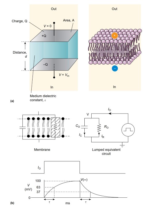
Figure 3. Electrical equivalent and voltage response of the cell membrane. (a) The lipid bilayer (right) acts like an ideal capacitor (left) that separates a charge, Q, on the two conducting plates, separated by a distance, d. The charge separation gives rise to a Voltage (V) across the capacitor (C), related by the equation Q=CV
The lipid can support a different distribution of charges, or a different potential on each side. In a perfect capacitor, this charge separation would be maintained without decrement. However, the cell membrane contains ion channels that act as a resistor to allow the flow of charge (current) across the membrane. Therefore, the membrane is like a leaky capacitor.
When charge is moved from one side to the other, via ionic current flow through open ion channels, the voltage on the two plates of the capacitor (the intracellular and extracellular surface) starts to change, but the change in Vm is not instantaneous. Current flows through the capacitive element of the circuit as the voltage across the capacitor changes. A new voltage difference is eventually established across the membrane, with an amplitude dependent on the membrane current, Im and the membrane resistance, Rm, as given by Ohm's law.
Although the current is applied virtually instantaneously as ion channels rapidly open and close, the change in Vm changes with a membrane time constant (t), given by the product of the resistance and capacitance of the circuit. Figure 3 demonstrates the electrical circuit equivalent for a cell membrane, and the time course of a change in Vm when current flows into a cell.
Date added: 2024-06-13; views: 576;