Precision Dimensions. Tight Seating, Overhang
The actual bearing engineering work concentrates not only on the selection of the bearing type, but also on precision dimensioning:
- Tight seating, overhang
- Bearing play
- Progress of bearing thickness around the circumference, gap at the bearing shell ends
- Surface properties, shapes, and positioning tolerances at the ends
Tight Seating, Overhang. The bearing force has to be transferred to the housing. To do so, it is necessary that the bearing be seated firmly in the housing, to reliably suppress the relative motions resulting from the pulsating load. This tight seating in the radial bearing is affected by the excess diameter and the so-called “crush height,” Sn, at the ends of the bearing shells, Fig. 7-260. The tabs or pins normally used to ensure correct positioning of the bearing are not suitable for fixing the bearing.
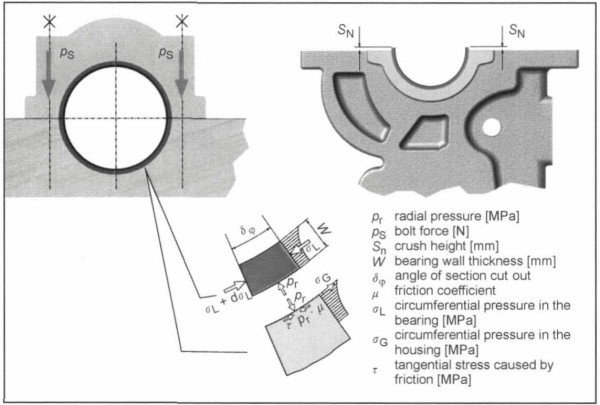
Fig. 7-260. Excess diameter and installation strains
The limits are, on the one hand, sufficient radial pressure (see Fig. 7-260) and, on the other hand, tangential strain that can be tolerated by the bearing shell without great plastic deformation. All standard bearing metals are overtaxed at the low bearing thicknesses prevailing today; a steel backing shell is required to provide sufficiently tight seating.
An engine bearing thus is made of a composite material incorporating steel and the actual bearing metal, with or without any additional coating, depending on the composition and particulars of the employment. Only in isolated cases, such as in large wrist pin bushings, can a single, solid material be used.
The low-alloy steels required in bearing manufacture have a maximum compression yield point of 360 N/mm2; this dictates a lower limit for bearing thickness, at about 2.5% of the diameter.
Of particular significance is temperature development in aluminum housings. Because of the differing degrees of thermal expansion for steel and aluminum, there is a reduction as temperatures rise; this can even lead to a loss of the preload. At lower outside temperatures, by contrast, the strength limits for the bearing shell and/or the bore may be exceeded.
In such cases the area immediately around the bearing is stiffened by sintered or cast steel components that are cast in situ. The global models for press fit calculations are no longer adequate when engineering composite bearings; local strains and deformations have to be ascertained using finite element methods.
Bearing Play. Bearing play is the most important, user-definable magnitude in bearing design. A smaller amount of clearance, nominally, creates greater hydrodynamic loadbearing capacity and—because of to the greater damping to counter displacement—better acoustic conditions. In contrast, at larger bearing play the lubricating oil throughput rises excessively (more than with the square of the clearance); the bearing becomes more tolerant of deformations and disturbances.
Thus, one sets the value for minimum play to be as small as possible while still ensuring operational reliability. The maximum play results from the manufacturing tolerances for bearing wall thickness (6 to 12 μm) and for the adjoining components and can become unacceptably high for small engines where D < 60 mm. Classification of bearing thickness is often a more favorable method than more exact manufacturing to limit the tolerance in play.
As for the press fit, mastering bearing play for aluminum housings is difficult. Across the operating temperature range there is an unacceptable amount of change from, for instance, 15 μm at — 30°C to as much as 120 μm at 130°C (at 50 mm diameter). Limiting maximum play requires more exact classification in which the bore, shaft, and play are associated one with another.
Wall Thickness, Clearance at Ends. An undisturbed, perfectly cylindrical bore is ideal for the bearing function. The strains resulting from bearing installation and inertial forces usually, however, cause a bore that is not a true circle; this is compensated by a continuous change in bearing shell thickness, from the center to the ends. When bearings are split into two semicircular shells, a gap some millimeters in length and about 5 to 15 μm in depth equalizes the differing thicknesses for the shells. Figure 7-261 shows typical values.
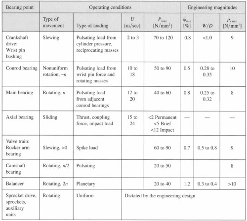
Fig. 7-261. Characteristic values and typical guideline values for the most important bearing locations
Also essential to uninterrupted bearing function is the correct design of the bore and journals in regard to alignment, roundness, crowning, waviness, and surface roughness. Reference is made here to the applicable engineering guidelines and standards.
Acceptable boundary values are applied when selecting the type of bearing, which is done in consideration of loading and other peripheral conditions. The loading limits and the characteristics for use in the normal bearing designs are described in greater detail at Section 7.19.4. It is important that simultaneous development be carried out by the bearing maker right from the engine’s draft design stage.
Date added: 2024-07-30; views: 552;