
Shallow-Water Waves: Refraction, Diffraction, and Navigation
Shallow-Water Wave Dynamics. As a deep-water wave approaches the shore and moves into shallow water, the reduced depth begins to affect the shape of the orbits made by the water particles. The orbits gradually become flattened circles, or ellipses (fig. 9.11). The wave begins to "feel" the bottom, and the resulting friction and compression of the orbits reduce the forward speed of the wave. Remember that (1) the speed of all waves is equal to the wavelength divided by period, and (2) the period of a wave does not change. Therefore, when the wave "feels bottom," it slows, and the accompanying reduction in the wavelength and speed results in increased height and steepness as the wave's energy is condensed in a smaller water volume.
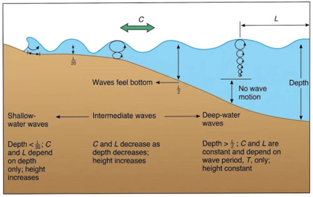
Fig. 9.11. Deep-water waves become intermediate waves and then shallow-water waves as depth decreases and wave motion interacts with the sea floor.
Transition to Shallow-Water States. When the wave finally enters water with a depth of less than one-twentieth the wavelength (D < L/20), the wave becomes a shallow-water wave (fig. 9.12). While the length and speed of a deep-water wave are determined by the wave period, the shallow-water wave's length and speed are controlled only by the water depth. Here the wave and speed length are determined by the square root of the product of the acceleration due to gravity (g) and depth (D): C = √(gD) or C = 3.13 √D, or L = 3.13 √D · T.
When the condition for a shallow-water wave is met, the orbits of the water particles are elliptical; they become flatter with depth until, at the sea floor, only a back-and-forth oscillatory motion remains (fig. 9.12). Note that the horizontal dimension of the orbit remains unchanged in shallow water. See appendix C for a more complete equation and the method used to calculate approximations of shallow-water wavelength and celerity.
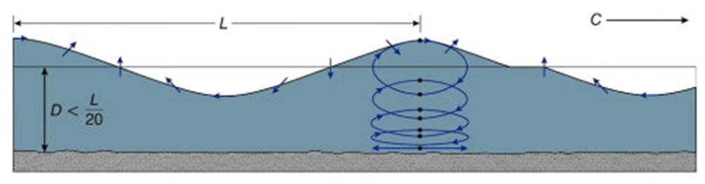
Fig. 9.12. Shallow-water wave particles move in elliptic orbits. The orbits flatten with depth because of interference from the sea floor.
Intermediate Wave Dynamics. When the water depth is between L/2 and L/20, the speed of the wave is also slowed. Waves in this depth range are called intermediate waves. There is no simple algebraic equation to determine the speed of these intermediate waves. Methods for working with intermediate waves using the full wave-speed equation will be found in appendix C.
Refraction of Coastal Waves. Waves are refracted, or bent, as they move from deep to shallow water, begin to feel the bottom, and change wavelength and wave speed. When waves from a distant storm center approach the shore, they are likely to approach the beach at an angle. One end of the wave crest comes into shallow water and begins to feel bottom, while the other end is in deeper water. The shallow-water end moves more slowly than that portion of the wave in deeper water. The result is that the wave crests bend, or refract, and tend to become oriented parallel to the shore.
This pattern is shown in fig. 9.13. The wave rays drawn perpendicular to the crests show the direction of motion of the wave crests. Note that the refraction of water waves is similar to the refraction of light and sound waves, described in chapter 4.
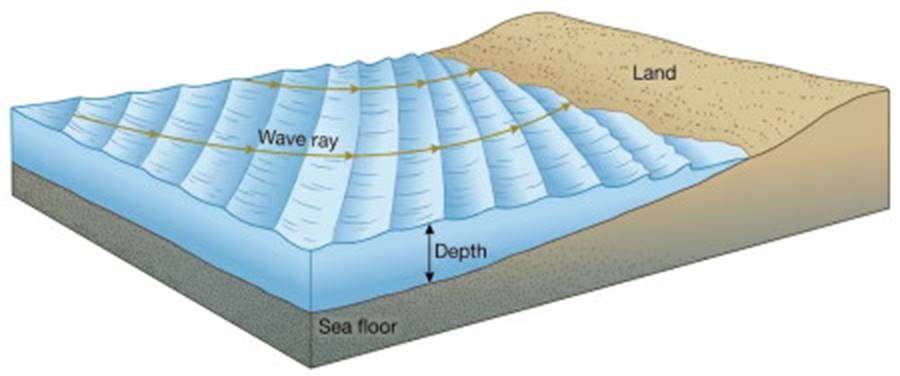
Fig. 9.13. Waves moving inshore at an oblique angle to the depth contours are refracted. One end of the wave reaches a depth of L/2 or less and slows while the other end of the wave maintains its speed in deeper water. Wave rays drawn perpendicular to the crests show the direction of wave travel and the bending of the wave crests.
Coastal Refraction Patterns. When waves approach an irregular coastline, with headlands jutting into the ocean and bays set back into the land, there is often a submerged ridge seaward from a headland and a depression in front of a bay. When shallow-water waves approach this coastline, the portion of the wave crest over the ridge slows down more than the wave crests on either side. The crests wrap around the headland in the pattern shown in figure 9.14. This refraction pattern results from the shortening of the wavelengths and focuses wave energy on the point of the headland. Since wave energy is proportional to the wave height, the waves gain in height as their wavelength is shortened over the submerged ridge, and more energy is expended on a unit length of shore at the point of the headland than on a unit length of shore elsewhere.
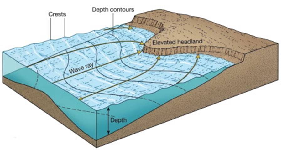
Fig. 9.14. The energy of waves refracted over a shallow submerged ridge is focused on the headland. The converging wave rays show the wave energy being crowded into a small volume of water, increasing the energy per unit length of wave crest as the height of the wave increases.
The central area at the mouth of the bay is usually deeper than the areas to each side, so the advancing waves slow down more on the sides than in the center. Because the wavelengths remain long in the center and shorten on each side, the wave crests bulge toward the center of the bay. The waves in the center of the bay do not shorten as much; therefore, they have less height and less energy to expend per length of shoreline.
This pattern is shown in figure 9.15. The result is an environment of low wave energy, providing sheltered water in the bay. Overall, this unequal distribution of wave energy along the coast results in a wearing down of the headlands and a filling in of the bays, as the sand and mud settle out in the quieter water. If all coastal materials had the same resistance to wave erosion, this process would lead in time to a straightening of the coastline; but the rocky structure of many headlands resists wave erosion, and therefore the cliffs remain.
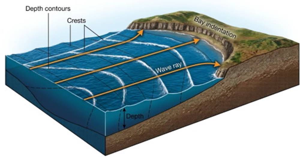
Fig. 9.15. Waves refracted by the shallow depths on each side of the bay deliver lower levels of energy inside the bay. The diverging wave rays show the spreading of energy over a larger volume of water, decreasing the energy per unit length of wave crest as the wave height decreases.
Reflection and Interference. A straight, smooth, vertical barrier in water deep enough to prevent waves from breaking reflects the waves (fig. 9.16). The barrier may be a cliff, steep beach, breakwater, bulkhead, or other structure. The reflected waves pass through the incoming waves to produce an interference pattern, and steep, choppy seas often result. If the waves reflect directly back on themselves, the resulting waves appear to stand still, rising and falling in place.
If waves are reflected from a curved vertical surface, the curve may spread the reflected wave rays, dispersing the wave energy, but if the surface curves so that the reflected wave rays converge, the energy is focused. This situation is similar to the reflection of light from curved mirrors. Great care must be taken in designing walls and barriers to protect an area from waves to be sure that the energy of reflected waves is not focused in such a way that another area will be damaged.
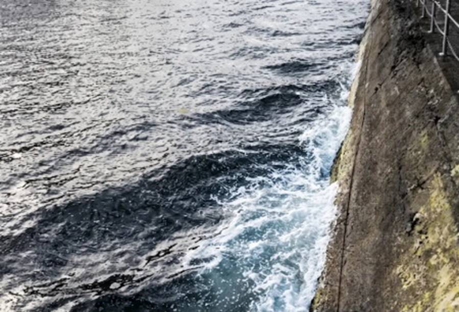
Fig. 9.16. The wave from a ship's wake is reflected from a concrete wall. The principal wave is moving from lower left to upper right of the photograph. The reflected wave is moving from lower right to upper left. A checkerboard pattern is formed as the principal wave and reflected wave move through each other at approximately right angles.
Wave Diffraction Phenomena. Another phenomenon that is associated with waves as they approach the shore or other obstacles is diffraction. Diffraction is caused by the spread of wave energy sideways to the direction of wave travel. If waves move toward a barrier with a small opening (fig. 9.17a), some wave energy passes through the small opening to the other side. Once the waves have passed through the opening, their crests decrease in height, radiating out and away from the gap. A portion of the wave energy is diffracted, transported sideways from its original direction.
This effect is shown in figure 9.17a. If more than one gap is open to the waves, the patterns produced by the spreading waves from the openings may intersect and form interference patterns as the waves move through each other (fig. 9.17b).
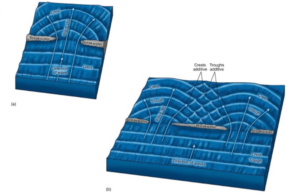
Fig. 9.17. Diffraction patterns produced by waves passing through narrow openings (a, b). Note the interference pattern produced when diffracted waves interact (b).
If the waves approach a barrier without an opening, diffraction can still occur. Energy will be transported at right angles to the wave crests as the waves pass the end of the barrier (fig. 9.18). Note that the pattern produced is one-half of the pattern observed when the waves pass through a narrow opening, as in figure 9.17a. Energy is transported behind the sheltered (or lee) side of the barrier. This effect is an important consideration in planning the construction of breakwaters and other coastal barriers intended to protect vessels in harbors from wave action and possible damage.
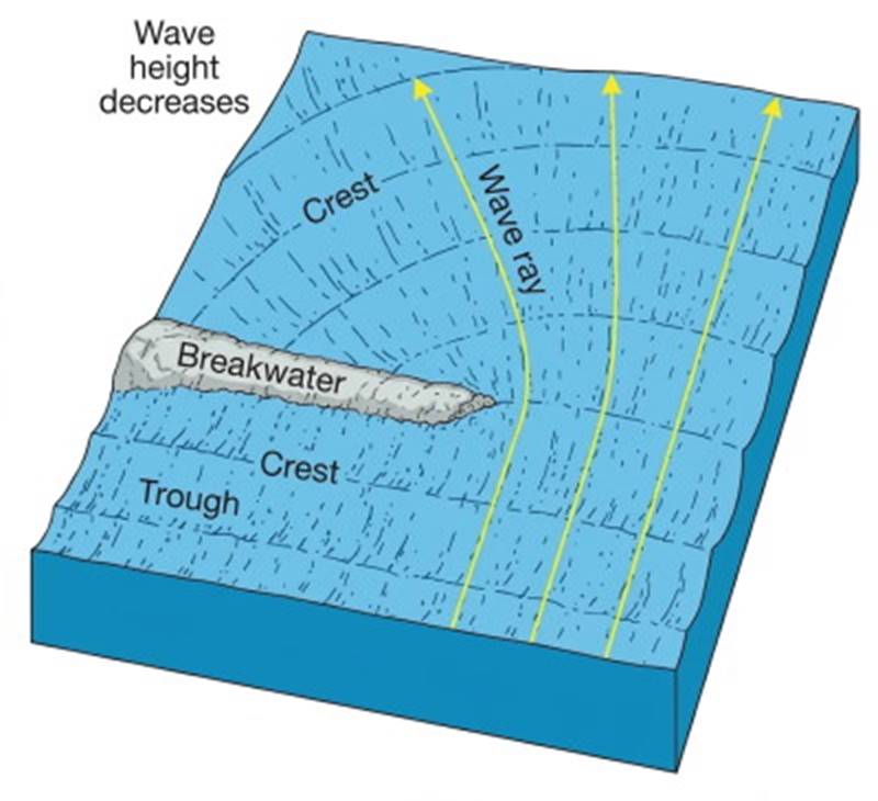
Fig. 9.18. Diffraction occurs behind the breakwater.
Navigational Applications of Wave Dynamics. In areas of the world where the winds blow steadily and from one direction, as in the trade wind belts, waves at sea are very regular in their direction of motion, and this regularity allows a vessel to maintain a constant course relative to the waves. Because waves change speed, shape, and height with water depth, and because waves change direction and pattern because of refraction, diffraction, and reflection, it is possible to deduce the presence of shoals, bars, islands, and coasts from the changes in wave patterns.
Careful direct observation of wave patterns, or the sensing of wave patterns through the motions of a small craft, even at night, allows the detection of a change in the angle between waves and wind direction or a change in the wave pattern. Although these changing patterns are subtle, they can be detected many miles from land and can be used to bring a small vessel to shore when no landmarks are visible.
Traditional Polynesian Navigation. The Polynesians of the past lived with the sea; it was their home, and they were acutely sensitive to its changes. They made long voyages in their small canoes using their knowledge of wave patterns. They had no theory to explain these patterns, but they understood their association with winds, shores, and islands.
Combining their knowledge of star positions, cloud forms over land and sea, and bird flights with their knowledge of waves, they sailed many hundreds, even thousands, of miles across the open ocean to reach their destinations. No navigational tools were required other than charts constructed from twigs and shells, showing island positions relative to stars, wind direction, and swell. An example of such a chart is found in prologue figure II. These peoples learned by living with and observing nature in an area where nature cooperated by behaving in regular and predictable ways.
Date added: 2026-11-09; views: 10;