Flywheel Bolt. Camshaft Bearing Cap Bolt. Oil Pan Attaching Screws
Flywheel Bolt. Because of the engineering design there is a relatively small pitch circle at the crankshaft. During assembly it is necessary to ensure that there is sufficient clearance between the bolts to accommodate the tightening tool. The bolts are all tightened simultaneously, using a multispindle tool and using the 0.2% offset limit as the control variable. This is also done because shorter clamping lengths (e.g., 7 mm) are present.
Because of the narrow clearance between the crankshaft journal and the flywheel, the bolt heads are not as high as the standard heads. To be sure that the required torque can be applied safely and positively, a twelve-pointed (bihexagonal) head or a hexalobar head or, if necessary, an inside, multispline socket is used at the head. When oil is supplied by runners inside the crankshaft, the bolts used to seal against oil leaks are provided with a microencapsulated sealing adhesive or with an all-round nylon coating.
Some engine manufacturers still tighten down flywheel bolts under torque control, and then snug them down manually.
In the dual-mass flywheels that are used more frequently today, the module is delivered to the vehicle manufacturer complete with the bolts and is then assembled as a unit. The bolts are tightened down with a multispindle power driver, through bores in the clutch plate spring and the clutch disk.
Camshaft Bearing Cap Bolt. This threaded connection usually uses collared screws that are similar to the standardized styles, in sizes of M 6, M 7, and M 8 for passenger car engines and M 10 and M 12 for utility vehicle engines.
Since during torque-controlled tightening, there is the hazard that differing clamping forces could be imposed on the camshaft bearings, the rotation-angle-controlled technique is used to a greater extent to achieve defined preload values. A special technique used by some car makers is to screw grub screws into the cylinder head; the bearing cap is then positioned and fixed with nuts.
Oil Pan Attaching Screws. The oil pan is also secured to the engine block with collared screws similar to the standardized styles, Fig. 7-329 (outside or inside socket wrench application, M 6, M 7, M 8 screws). To achieve complete freedom from leaks, the surface pressure must be uniform across the entire oil pan gasket.
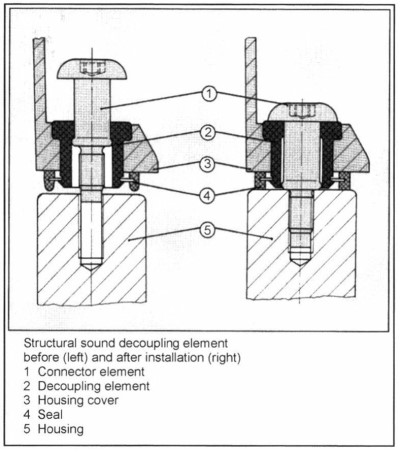
Fig. 7-329. Oil pan screw with structural acoustic decoupling element (depiction before [left] and after [right] assembly) (KAMAX Company)
This is achieved with the smallest possible screw diameter that thus exhibits appropriate flexibility and with a suitably large collar diameter or a washer, where the screw forces are introduced uniformly. In addition, a large number of screws is needed so that when forces are introduced there are large overlaps in the “pressure cone” in the area of the seal. In spite of the great demands for tightness, this connection point is considered to be trouble-free.
The screws are, as a rule, tightened under torque control (using a multispindle power screwdriver unit). To ensure that the oil pan is not canted, tightening is started at the middle of the engine block, continuing outward from there.
Ribs on the lower surface of the engine block reduce noise propagation. The oil pan itself is a source of high noise emissions because of its large surface area and low weight. Here the solution involving structural noise decoupling by the mounting screws used for the oil pan is a viable option. Widespread use has not been implemented because of the costs involved.
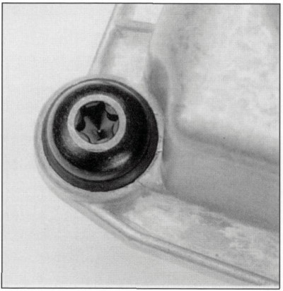
Fig. 7-330. Oil pan screw with inside hex lobes and collar (KAMAX Company)
In order to cut costs, the market is exhibiting a trend to preassembling connector elements in system assemblies such as oil pans, valve covers, timing belt covers, etc. Here leading screw manufacturers are working on economical and space-saving preassembly solutions such as, for example, using self-tapping screws. Another solution, which at the same time could serve the interest of acoustic decoupling, employs a plastic bushing that is slipped over a special screw and is then premounted together with the component (Fig. 7-330).
Date added: 2024-07-30; views: 784;